
Direct answer: Above roughly 15 metres, the mast, its foundation and its maintenance method decide more of the 25-year cost than the luminaire datasheet does. Fix three things before comparing fixtures: the structural standard and the site wind speed, the illuminance and uniformity target for the surface below, and who services the heads – a lowering headframe or a crane every visit. Get those wrong and the cheapest fixture quote becomes the most expensive installation on the site.
When a project crosses into high-mast territory
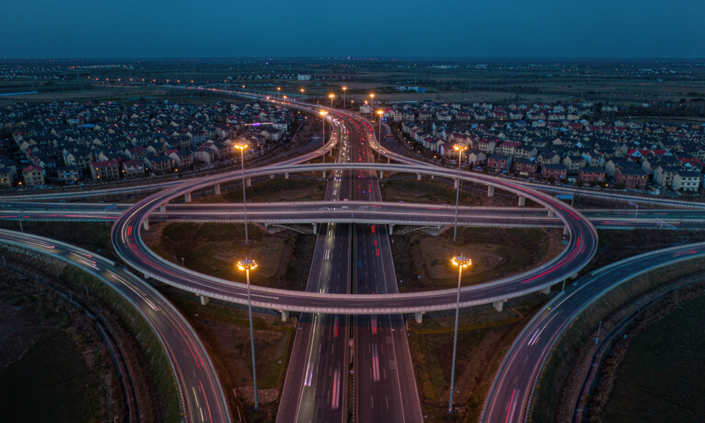
There is no single legal definition, but in practice the industry treats roughly 15 metres as the line where the design changes character: bucket-truck access gets awkward, pole self-weight and wind loads start to drive the steel, and one mast replaces dozens of columns. Supplier catalogues commonly run 15 to 45 metres, with 25 to 30 metres as the standard offering for highways, ports and logistics hubs; interchange projects are commonly quoted at 30 to 40 metres with mast spacings of 250 to 350 metres, and large car parks around 20 to 25 metres. Every mast you delete removes a foundation, a cable run and a service point – but every remaining mast concentrates more light, more weight and more failure risk in one structure, which is why the decisions below matter more than the fixture wattage.
The standards stack: structure and light are separate documents
Two independent families of standards govern a high-mast installation, and tenders that merge them produce unbuildable specifications.
- Structure: lighting columns and brackets to the EN 40 series, with wind actions calculated under Eurocode EN 1991-1-4. In the United States the equivalent reference is ASCE 7. The manufacturer must supply signed, site-specific structural calculations – not a generic certificate.
- Light: EN 13201 for road lighting classes, EN 12464-2 for outdoor workplaces such as yards, storage and loading areas, and ICAO Annex 14 Volume I with the Aerodrome Design Manual (Doc 9157 Part 4) for airport aprons. In the EU the aviation requirements are transposed through EASA CS ADR-DSN.M.750, and national implementations such as the UK’s CAP 168 may strengthen them.
ICAO provisions are recommendations, not law; they bind through national adoption. That is also why an apron design and a logistics yard design can use the same mast and completely different compliance documents.
Illuminance and uniformity targets worth writing into the spec
| Surface | Standard | Average illuminance | Uniformity | Extra requirement |
|---|---|---|---|---|
| Aircraft stands | ICAO Annex 14 Vol I | At least 20 lx horizontal | Average-to-minimum no worse than 4:1 | At least 20 lx vertical at 2 m in relevant directions |
| Other apron areas | ICAO Annex 14 Vol I | At least 50% of the stand average | 4:1 | Glare limited for tower, pilots and ground crews |
| Parking areas | EN 12464-2 | 5 / 10 / 20-25 lx for low, medium and high usage | Uo at least 0.25 | Values differ between the 2014 and 2022 editions – check the edition your authority adopts |
| Open-air storage and general industrial areas | EN 12464-2 | 20 lx | Uo at least 0.25 | – |
| Loading and unloading areas | EN 12464-2 | 50 lx | Uo at least 0.40 | Vertical illuminance on the vehicles |
Uniformity is where high-mast schemes fail, not averages. A grid that passes 20 lux on average can still carry dark patches between masts, and on an apron that fails the 4:1 ratio outright. For how design documents get checked, see our guide to reviewing a lighting layout report.
Aiming, optics and the two-direction rule
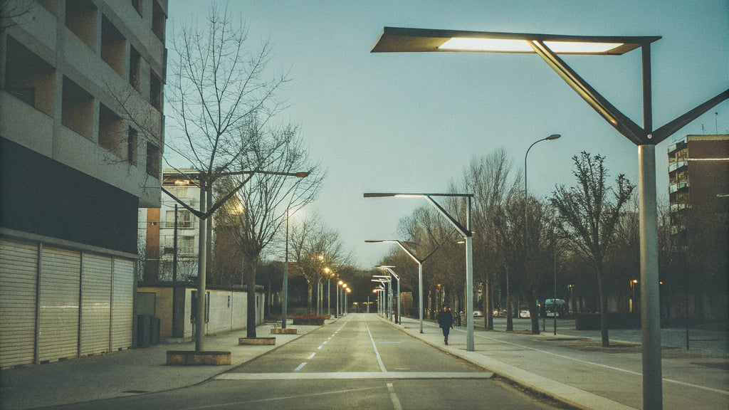
ICAO asks that each aircraft stand receive light from two or more directions to minimise shadows – a shadow requirement disguised as an aiming rule. A stand lit from one side measures fine on the horizontal grid and still leaves the far side of a fuselage in shadow, which is why the vertical illuminance calculation at 2 metres, in the relevant directions, belongs in the submission. The same logic transfers to container yards and loading aprons where people work beside tall obstacles.
Two further aiming habits from practice: keep the spacing-to-mounting-height ratio in the commonly used 3:1 to 5:1 band as a starting point, then let the photometric model – not habit – set the final positions; and reserve narrow beams for long throws. Wide-beam floods on a 30 metre mast waste light as glare, and a tilt change of two degrees can move the uniformity figure measurably. For the optics trade-offs behind these choices, our comparison of reflector and lens optics covers the fundamentals, and lumen depreciation and maintenance factors explains why the as-new lux number overstates what the site will receive in year five.
Wind loading: the calculation that cannot be generic
A high mast is a slender cantilever with a bundle of sails on top. The design wind speed depends on the site, the terrain category and the return period, so there is no single number to quote – there is a calculation, per site, per pole. The structural package should include the effective projected area of the luminaire ring and its brackets, drag coefficients for the pole cross-section, the foundation design against the site’s geotechnical report, and hot-dip galvanising to ISO 1461, where zinc coating thicknesses around 85 micrometres are commonly specified for long outdoor service. At the taller end of the range, vortex-shedding behaviour also gets checked.
The purchasing consequence is simple: reject any bid where the “structural documentation” is a stock certificate instead of signed calculations for your coordinates, your wind zone and your fixture layout. A pole that survives the tender and fails in the first typhoon-season storm was never cheaper.
The lowering device decision
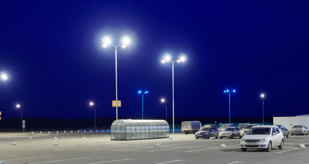
A winch-based lowering system drops the luminaire ring from the pole top to around 1.5 metres above ground, so heads are serviced from the ground instead of a crane or a lift truck. Suppliers commonly quote the device at USD 3,000 to 8,000 per mast against crane service visits commonly quoted at USD 1,000 to 2,000 each before traffic management and area closures are counted. Over a 25 to 30 year pole life with routine re-aiming, driver swaps and relamping, the arithmetic usually favours the device wherever lift trucks cannot reach the height or closures are unacceptable – ports, aprons, live carriageways.
Specify the lowering route when at least one of these is true: mounting height exceeds what local lift trucks reach; the site cannot be closed for maintenance windows; or the fixture count per mast is high enough that every visit is a major intervention. Where none of these hold, a plain headframe and a hired crane can be the cheaper life-cycle choice – the mistake is deciding this after the pole is ordered, because the headframe geometry and the cable system are designed into the pole, not bolted on.
Budgeting the installation over 25 years
Pole suppliers commonly quote the following ranges. They are market references, not standards – height, wind zone and fixture count move every line.
| Line item | Commonly quoted range | What moves it |
|---|---|---|
| Complete high-mast installation: pole, foundation, ring, LED fixtures | USD 15,000 to 80,000 per mast | Height, fixture count, wind zone |
| Reference 30 m pole with six LED floods, installed | USD 25,000 to 40,000 | Site access, foundations, optics |
| Winch-based lowering device | USD 3,000 to 8,000 per mast | Ring weight, travel speed, safety features |
| Crane or lift-truck service visit | USD 1,000 to 2,000 each | Plus closures, traffic control, re-aiming time |
| LED retrofit versus HPS on energy | Commonly 60% or more saved | A 400 W LED class replaces a 1,000 W HPS class head |
Two controls decisions compound those savings over the decades: scheduled dimming scenes that drop output when traffic is light, and remote fault reporting so one failed head does not wait for the next full inspection. Energy is the line item that grows with every tariff revision; the structure is the one that punishes shortcuts.
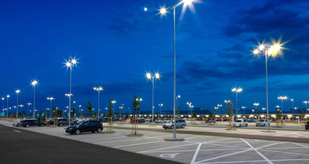
Before ordering, close this checklist: signed site-specific wind calculations including the ring’s effective area; photometric results for average, minimum and uniformity on the actual grid, plus vertical illuminance at 2 metres where the ICAO logic applies; the lowering-device specification written into the pole drawing; galvanising certificate; and a spare-driver package agreed at order time, not after the first night shift calls about a dark mast.
Frequently asked questions
What mounting height counts as high mast?
No standard draws a hard line, but around 15 metres the design changes: lift-truck access, structural demands and per-mast coverage all shift. Supplier ranges commonly run 15 to 45 metres, with 25 to 30 metres typical for highways, ports and logistics hubs.
Does ICAO Annex 14 apply to my port or distribution yard?
No – it is aviation-specific and binds through national adoption. Its logic still travels well: uniformity ratios, the two-direction shadow rule and vertical illuminance at 2 metres are good templates for any yard where people work beside tall obstacles. The governing documents for non-aviation sites are EN 12464-2 and, on roads, EN 13201.
Do I always need a lowering device?
No. If lift trucks reach the height and closures are cheap, crane servicing can be the lower life-cycle cost. Specify the lowering route when heights exceed local reach, closures are unacceptable, or each visit is a major intervention – and decide before the pole is ordered.
What wind speed should the pole be designed for?
There is no universal figure. The design wind speed comes from the site’s wind zone, terrain and return period, applied through EN 40 with EN 1991-1-4 in Europe or ASCE 7 in the US. Demand signed, site-specific calculations that include the fixture ring’s effective projected area.
How is uniformity verified after installation?
With grid-based measurements using a calibrated lux meter: record the grid, compute the average-to-minimum ratio, and compare against the target – 4:1 on aircraft stands under the ICAO recommendation, or the Uo figure from EN 12464-2. Add vertical measurements at 2 metres where the task demands it, and re-measure after any re-aiming.
