

Direct answer: Beam angle does not change how many lumens a fixture produces — it changes where they land. Before you buy, read four numbers from the photometric file: the beam angle (the cone where intensity stays above half its peak), the spacing-to-mounting-height ratio the optic supports, the center beam candlepower, and the uniformity the layout delivers against your target. Get those four right at your actual mounting height and the layout works. Get them wrong and no amount of extra wattage fixes the dark stripes between fixtures.
Most high-bay disputes start the same way: procurement compares lumens, watts and price, and the fixture that wins the spreadsheet is often the one whose optics put light in the wrong place. A 30,000-lumen fixture is not one product — at 60 degrees, 90 degrees and 120 degrees it is three completely different lighting systems. Here is how to read the distribution data and turn it into a layout you can defend before the first ladder goes up.
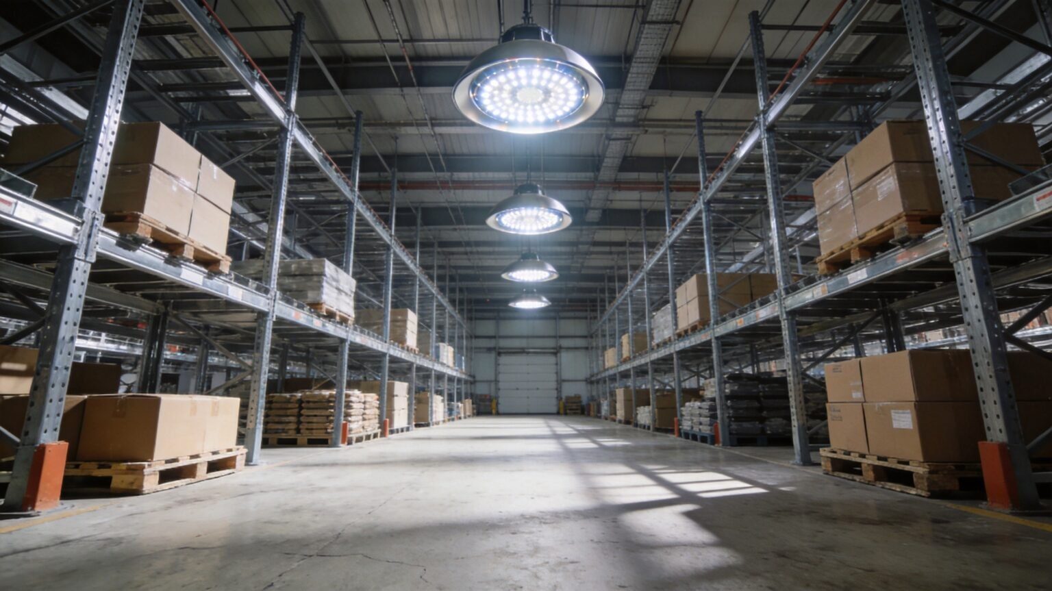
Beam angle is a floor pattern, not a brightness dial
By IES convention, the beam angle is the full cone across which intensity stays at or above 50% of the peak; the field angle is where it falls to 10%. The total lumens are identical — the footprint changes. The geometry is simple: the coverage circle on the floor is approximately twice the mounting height times the tangent of half the beam angle.
| Optic class | Typical full angle | Approx. coverage circle at 25 ft mounting height | Where it belongs |
|---|---|---|---|
| Narrow | 60° | about 29 ft | Tall racking aisles, 35 ft+ ceilings |
| Medium | 90° | about 50 ft | General warehouse 20–30 ft, manufacturing |
| Wide | 120° | about 87 ft | Open floor below 20 ft, low-bay retrofits |
Coverage circle is not spacing. You plan for overlap between neighboring beams — a rough 30% overlap at the work plane is a common starting point — because the edges of each cone are, by definition, where the output has already fallen by half. Spacing the fixtures at the full coverage diameter is how warehouses end up with a polka-dot floor.
The four numbers that predict the result
| Number | What it tells you | What should make you stop |
|---|---|---|
| Beam and field angle | The shape of the cone and where intensity actually collapses | A “120°” optic whose wide reading comes only from the 10% field angle — check both numbers |
| Center beam candlepower (CBCP) | The punch directly under the fixture, in candelas | The same lumen package can vary by a factor of three or more in CBCP between 60° and 120° versions — the lumens alone tell you nothing |
| Spacing criterion (S/MH) | The maximum spacing-to-mounting-height ratio before uniformity breaks down | Not published at all — ask for the IES file and walk away from suppliers who cannot produce one |
| Efficacy with light loss assumptions | Maintained light, not day-one light | Layouts quoted on initial lumens with no maintenance factor — dust and depreciation are coming either way |
All four live in the photometric file — LM-63 ASCII or the newer TM-33 XML — that any competent supplier can hand over with the quote. Knowing how to sanity-check that file and the LM-79 report behind it is a fifteen-minute skill that prevents the most expensive mistake in industrial lighting: buying a number instead of a distribution.

Spacing to mounting height: the ratio that predicts dark stripes
The spacing-to-mounting-height ratio (S/MH) is the single most useful number in layout planning. It is the maximum distance between fixtures, expressed as a multiple of the height from fixture to work plane, at which the layout still holds acceptable uniformity. Typical working ranges by optic:
| Optic | Typical S/MH | Practical grid at 25 ft mounting height |
|---|---|---|
| Narrow 60° | 0.8–1.0 | 20–25 ft |
| Medium 90° | 1.0–1.3 | 25–32 ft |
| Wide 120° | 1.3–1.5 | 32–37 ft |
Treat these as starting points, not guarantees — the fixture’s own photometry and the uniformity target set the real limit. Two field corrections matter. First, measure mounting height from the floor to where the fixture will actually hang, not to the roof deck; pendants and cable suspensions routinely drop fixtures two to five feet, and that delta changes the ratio meaningfully. Second, rows of fixtures over aisles usually need to be held closer to one times the mounting height along the row, regardless of what the open-floor grid allows.
The uniformity targets the layout has to hit
A layout is not finished when the average footcandle number is right. It is finished when the dimmest task point is acceptable. US practice, drawing on IES handbook values, commonly targets an average of 10–30 footcandles for general warehouse work — around 20 fc is a frequent open-floor target, with 30 fc and up for picking and packing — and a minimum-to-average uniformity of at least 0.4 in storage areas and 0.6 in task areas. A max-to-min ratio of 3:1 or better is a common ceiling for the same purpose.
European projects face a stricter, codified version. EN 12464-1:2021 sets maintained illuminance, uniformity and glare limits directly:
| Zone | US practice target | EN 12464-1:2021 | Uniformity |
|---|---|---|---|
| Bulk / general storage | 10–20 fc | 100 lx | Uo ≥ 0.40 |
| Racking gangways, manned | 10–20 fc | 150 lx | Uo ≥ 0.40 |
| Picking and packing | 30 fc | 300 lx | Uo ≥ 0.60 |
| Loading dock | 30–50 fc | 150 lx | Uo ≥ 0.40 |
| Quality control | 50–75 fc | 750 lx | Uo ≥ 0.70 |
One more constraint sits above all of it: the energy code. Warehouse lighting power allowances in recent editions of ANSI/ASHRAE/IES 90.1 sit roughly in the 0.4–0.66 W/sq ft range depending on the edition and compliance method your jurisdiction adopted — so adding fixtures to fix a uniformity problem can fail plan review even when the footcandles are perfect. The way out is better optics, not more fixtures.

Why narrower optics are not automatically more efficient
The intuition trap runs like this: a narrow beam concentrates light, so it must deliver more footcandles per watt. The geometry says otherwise once you look at the whole floor. The solid angle inside a 60° cone is roughly a quarter of the solid angle inside a 120° cone, so the same lumen package produces around three to four times the peak intensity — but it covers a fraction of the area. If the fixture spacing cannot close up to match the narrow cone, the lumens saved under each fixture are simply missing between fixtures, and uniformity collapses.
That is also why “upgrading” a layout by swapping optics without recalculating is a coin flip. A wide-beam layout at 30-plus feet sprays the upper walls and racking tops with light that never reaches the task plane. The same building re-solved with medium optics at tighter spacing frequently uses fewer fixtures and measures better — which is the actual definition of efficiency: lumens landing on the task plane divided by lumens purchased.
Aisle lighting is a vertical illuminance problem
Open-floor logic fails in racking for a physical reason: the task is not on the floor. Picking means reading labels and barcodes on vertical rack faces, and EN 12464-1 addresses it directly with a 200 lx vertical requirement on rack faces. A symmetric round optic centered over a narrow aisle over-lights the floor and leaves the upper shelves in shadow — the classic failure is bright concrete, dark labels.
The fix is optical, not electrical: linear or asymmetric aisle optics mounted on the aisle centerline throw light onto the rack faces instead of the floor. One caution from controls and machine-vision integrators: overly narrow beams can produce saturated highlights that make barcodes hard for scanners to read, which is why a medium distribution often beats an aggressive narrow one in automated facilities. If your building mixes open staging and racking, mixed solutions usually win — wide or medium optics over open zones, aisle optics down the racking, one controls platform throughout.
Four layout mistakes no wattage can fix
- Designing from initial lumens with no light loss factor, so the installation measures well in week one and fails the audit in year three.
- Measuring to the roof deck instead of the fixture, and inheriting a spacing ratio that was never real.
- Copying the open-floor grid into the racking aisles, where the task is vertical and the beams need to run along the aisle axis.
- Ordering optics by wattage class instead of by the IES file — two fixtures with identical lumens and wattage can light the same building completely differently.
Frequently asked questions
What beam angle suits a 30-foot mounting height?
Usually narrow to medium — 60° to 90° — but the honest answer is derived, not memorized: take the optic’s spacing criterion, apply it to the real mounting height, and check the uniformity in a photometric layout before ordering.
How much overlap should there be between fixtures?
A common starting point is around 30% overlap of the beam patterns at the work plane. The real constraint is the uniformity target: minimum-to-average of 0.4 or better in storage, 0.6 in task areas.
Can I trust the manufacturer’s stated spacing?
Treat it as a claim until you see the IES file behind it. Run the layout in DIALux, AGi32 or Relux with your actual dimensions and reflectances — the software is cheap compared with rehanging a warehouse.
Does a wider beam save energy?
No. Beam angle redistributes lumens; wattage buys them. A wider optic can let you use fewer fixtures at low mounting heights, but at height it typically wastes light on walls and rack tops. Efficiency comes from matching the cone to the task plane.
What uniformity should a warehouse target?
Minimum-to-average of at least 0.4 for storage areas and 0.6 for picking and packing, with a max-to-min ratio of 3:1 or better as a common working ceiling. European projects must additionally meet the Uo and UGR limits written into EN 12464-1:2021 for each zone.
